
[Road of SKYSQUARE-041-] Strengthening the Heart of Power! Boosting from 30A to 50A and Expanding the Distribution Network ~Replacement~
- Feb 17
- 9 min read
![[Road of SKYSQUARE-041-] Strengthening the Heart of Power! Boosting from 30A to 50A and Expanding the Distribution Network ~Replacement~](https://static.wixstatic.com/media/fc32ca_964d7a0f20754cb7b6a398abb848eaa1~mv2.jpg/v1/fill/w_980,h_551,al_c,q_85,usm_0.66_1.00_0.01,enc_avif,quality_auto/fc32ca_964d7a0f20754cb7b6a398abb848eaa1~mv2.jpg)
Hello,
This is Nakajima from AZSTOKE Co., Ltd.
It is the purpose of this project.
Upgrade the studio's electrical capacity (amps) to deliver stable power to every corner of the field.
For this project,
The previous 30A (ampere) capacity was insufficient to run all equipment at full capacity.
This time, we will increase the main distribution panel's capacity to 50A and extend power to the outdoor facility via underground conduits.
Click here for a list of previous SKYSQUARE Road articles

■Table of Contents
1.The 30A Limit. “50A Step-Up” to Keep Creativity Flowing
The existing power supply for SKYSQUARE's prefabricated studio was rated at 30A.
At this capacity, running multiple pieces of equipment at full power while using air conditioning constantly carries the risk of tripping the circuit breaker.
Power loss is unacceptable in a professional recording environment.
Here is the design drawing visualizing this expansion plan.

As outlined in this plan, our mission this time is not only to increase the capacity within the prefabricated structure but also to supply power to the base across the vehicle passageway via the FEP conduit we buried last time.
With future field expansion in mind, we have decided to upgrade the capacity to 50A all at once this time.
2. Take safety precautions and make preparations.
Safety is paramount in electrical work.
First, wear dedicated insulated gloves as insulation monitoring and safety measures.
Since work will be performed near live wires, exercise extreme caution.

Prepare the feeder line connecting Outdoor Distribution Panel ① to Indoor Distribution Panel ②.
This wire is thick enough to handle 60A.
It's surprisingly heavy due to its considerable thickness.

The 16mm PF pipe won't fit, so I prepared a 22mm one and started inserting it.
I used a pull wire to feed the pipe through.
I tried inserting it directly once, but it didn't work well—that's when I understood why you need a pull wire.
It just stops midway and won't go through...
Despite various challenges, I managed to get it through the PF pipe.

3. Removal of existing 30A distribution panel. Demolition for complete replacement.
Before constructing the new system, we will first proceed with the task of completely removing the existing 30A distribution panel.


The first step in any electrical work is reliable voltage testing.
After turning off the main circuit breaker, use a voltage tester (checker) to confirm the circuit is de-energized.
Working based on assumptions directly leads to electric shock accidents, making this one of the most critical steps requiring utmost attention for a licensed electrician.

After confirming no voltage is present, disconnect all wires from the terminal block.
Organize each wire that previously supported circuits within the prefabricated structure one by one. While maintaining the markings applied in preparation for transitioning to the new panel, disconnect the wiring.

Finally, remove the main distribution panel from the wall.
This leaves the wall temporarily exposed, creating a foundation for installing the new 50A-rated panel.
Resetting the old equipment allows for rethinking the optimal layout, taking future maintenance needs into consideration.
4. Installation of new distribution panels. Infrastructure development to accommodate increased capacity.
We will install a new 50A-rated system—the new core component—in the space vacated by the old distribution panel.

This time, we selected a larger box size to accommodate future circuit expansions and facilitate easier maintenance.
To reduce on-site work time and improve installation accuracy, the internal breakers and terminal blocks are pre-assembled and delivered ready for installation.
The enlarged box is securely fastened to the wall surface, serving as a hub to distribute power to each circuit.


Next, proceed with wiring the main cable (primary power source) prepared in Step 2.
We route the thick main cable, capable of handling a 50A load, into the newly installed box with a smooth path and appropriate bend radius.
With terminal connections imminent, we position the cable along the shortest route with manageable tension.
This completes the preparation for connecting the power network: from the external power receiving facility to the studio interior, and then through the underground conduit to the field.
5. Unexpected accident. Not passing...
The cable routing work had been proceeding smoothly until we encountered a major problem.
When we attempted to pull the main cable through the pre-installed cable entry point in the prefabricated wall, the 50A-rated cable we had prepared turned out to be thicker than anticipated. It occupied all the available space inside the conduit.
The main cable itself managed to pass through, but there was absolutely no room to run auxiliary wires like the ground wire.
Forcing them through risked damaging the insulation, and compromising the infrastructure's safety was out of the question.
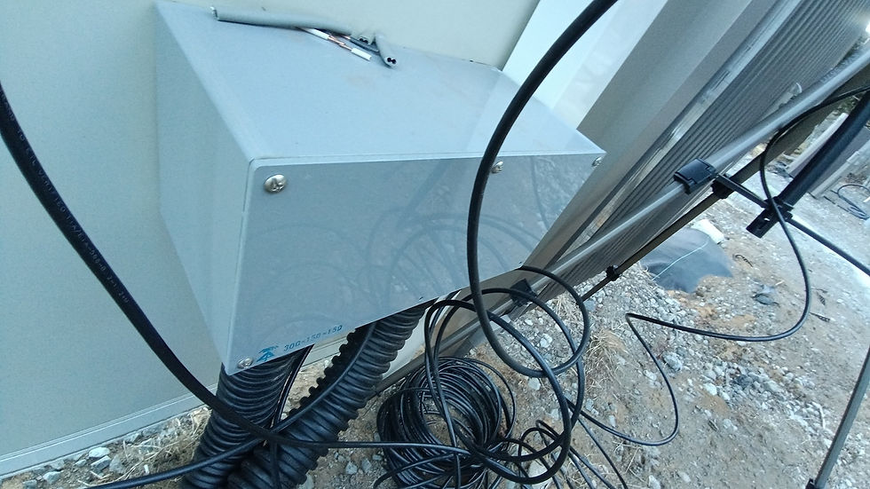
Therefore, we abandoned the existing route and made the urgent decision to create a new penetration hole in the wall. We carefully drilled the hole using a hole saw to secure the physical space needed for cable routing.
A small junction box with an entry hole at the bottom was installed in the opening.
This allows the thick main cable and other wires to be pulled inside smoothly while maintaining waterproofing.


Here is the completed installation.
Although an unexpected process arose due to an incident, it ultimately allowed us to establish a safer and more reliable route that avoids placing undue stress on the wiring.
This moment reaffirmed that “adaptability on-site” is also an indispensable skill in building SKYSQUARE.
6. Wiring work. Wrestling with 14sq wire.
Having completed the wall penetration and route securing, we are now moving on to the process of connecting the pulled-in main line to the newly installed distribution panel.
The 50A feeder wire has finally appeared inside the newly installed large box.
This is where my skills as an electrician come into play, but with a wire this thick, it won't be a simple task.

Drill holes in the box at appropriate positions and run the wires to the main breaker terminals.
Arrange the wiring neatly inside to avoid strain and ensure no excessive load is applied. However, the wires possess significant spring tension and rigidity, making them difficult to control with just finger strength alone.
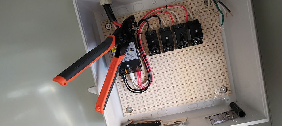
The most physically demanding part of this job was crimping the 14sq terminals.
To safely carry such a high current of 50A, this gauge of wire is essential. Using a specialized large crimping tool, you crush the terminals by putting your full weight into it, but they are surprisingly hard.
I crimped each one, one by one, with precision. Working in the confined space of the box tested the limits of my grip strength and endurance.
However, any slack in the crimp here could cause poor contact or even a fire, so absolutely no compromise is allowed.


After a struggle, all terminals were bolted securely to the main breaker.
Finally, a single, robust 50A power line connects from the external power receiving equipment to the heart of the studio. A final check was performed to ensure no terminals were loose, and the wiring is complete.
7. Consolidation of grounding systems. Efficiency gains through custom branch terminal blocks.
As part of this wiring expansion, we've also made an improvement to how the ground wires are handled. Instead of connecting ground wires from multiple devices or circuits haphazardly, we'll create a “branch” to neatly consolidate them in one location.

This terminal block was used to bundle multiple wires together for the ground connection.
By pre-processing and installing jumper wires beforehand, we prepared to efficiently and reliably consolidate multiple ground wires into a single grounding wire.
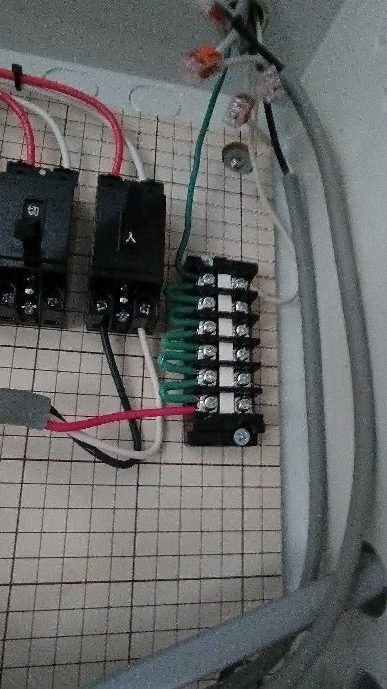
Here is how it actually looks when installed inside the distribution panel.
By using branch terminal blocks like this, it becomes easier to add circuits later and identify circuits during maintenance.
Although these parts are hidden, such meticulous construction ultimately contributes to the reliability and “beauty” of the infrastructure.
8. Outdoor wiring. Branch circuits from the main distribution panel.
The wiring for the main distribution panel is complete. Next, we will perform the branch wiring to distribute this power to each outdoor location.

The power drawn from the main breaker is branched to each sub-breaker for outdoor distribution.
Here too, to ensure reliable power supply and safety, crimp terminals are carefully installed one by one, and connections are made securely to prevent any loosening.

Next, secure a route for running wires from the distribution panel box to the outdoors.
Use a hole saw to cut an opening in the side of the box. Drill holes at precise locations according to the wire gauge and the size of the conduit.
This is a practical step: customizing the work to the site conditions rather than simply using off-the-shelf products.


The wiring exiting the box is secured along the prefabricated wall surface and routed outdoors.
Since this is exposed wiring, we lay it straight and securely using saddles and other fixtures, considering both aesthetic appearance and durability.
This line connects to the entrance of the “FEP conduit” buried 1.2 meters underground, which we painstakingly dug to reach last time.
9. Integration with underground infrastructure. From prefabricated units to outdoor distribution panels.
The wiring that has been running along the prefabricated wall from the main distribution panel finally burrows underground and connects to the underground infrastructure constructed previously.
Connect the FEP conduit raised from the ground to the wiring from the wall within the junction box.
As this point connects the above-ground and underground sections, ensure thorough waterproofing to prevent rainwater intrusion while maintaining a spacious layout that allows for future cable replacement.
Preparations are now complete to finally deliver 50A power to the conduit route buried at a depth of 1.2 meters.

Then, to the other outlet of the FEP conduit. We route the line to the outdoor distribution panel installed beyond the vehicle passageway and complete the wiring.
This completes the connection: a single, robust line now runs from the main distribution panel inside the prefab, deep underground, all the way to the field base.
With this “outdoor distribution panel” now complete, the environment where stable power can be secured instantly, anywhere within the vast SKYSQUARE, has become a reality.
SKYSQUARE Articles List
[Road of SKYSQUARE-038-] Quick purchase! New force! Pickup of used aerial work platform -buy it now-
![[Road of SKYSQUARE-040-] Multifunctional underground infrastructure construction record ~Line~](https://static.wixstatic.com/media/fc32ca_7661db59cf234542ba169f120e4d17d8~mv2.jpg/v1/fill/w_980,h_551,al_c,q_85,usm_0.66_1.00_0.01,enc_avif,quality_auto/fc32ca_7661db59cf234542ba169f120e4d17d8~mv2.jpg)
![[Road of SKYSQUARE-039-] The development of a huge 6-ton concrete component ~Stone~](https://static.wixstatic.com/media/fc32ca_9671510c8d5b493eb39ff32b5ce94b7d~mv2.jpg/v1/fill/w_980,h_551,al_c,q_85,usm_0.66_1.00_0.01,enc_avif,quality_auto/fc32ca_9671510c8d5b493eb39ff32b5ce94b7d~mv2.jpg)